|
|
|
 |
Tracy's Wheels |
|
"Don't believe anything I say; learn about what I say and prove it to yourself!"
by Tracy Jones
Tracy`s wheels Parts List
Date: 09/30/1999
|
Today, I picked up my wheels at the machine shop and the total cost of all four including material cost of 24.00 dollars came to $304.00.
I am going to use 3/4 inch MDO plywood for the top and bottom of the device and this came to $45.00 obtained at Home Depot.
I had them cut the 4 x 8 foot sheet (medium density board with thin overlay) in half using their skill saw with a standard blade.
This is the same board I've used in assembling the Enhancer and one lumber supply house called it sign board.
Home Depot said they sell it as counter top board. |
 |
 |
Tracy`s wheels Assemble Report 1
Date: 10/01/1999
|
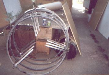
To find the center of my MDO board that will be used to house the device with one ľ inch board on bottom and one ľ inch board on top held together with plastic supports at the edge, I took a chalk string and stretched it from one corner to the other of the 4 x 4 foot board.
I then drilled a Ľ inch hole in the center where the strings crossed.
I normally work by myself, so unless otherwise noted, all work is completed solo.
I then took a 5/8 x 1/8 inch aluminum strip I use for a straight edge and placed a 5 x Ľ inch threaded bolt with two nuts on each side to hold the bolt in place leaving a one inch extension on the bottom end.
I then drilled a 1/8 inch hole in the strip 23 and 7/8 inch from the center of the bolt.
Due to the board being cut in half, you will lose some of the length because of the cut making the board shorter.
By using this measurement, you will have a complete circle with 1/8 to 1/4 inch left over for cutting.
Refer to photo #1 for layout.
I then found the half way mark on the manufactured end and drew a line to this mark from center and ten extended the line to the other side.
I did same on the side.
I now have a circle with 8 lines in it showing 8 equal quadrants.
By drawing a line from where the lines intersect the perimeter line, I then marked the center of this line and drew a line from this mark towards center.
This gives me 16 quadrants of which all are equal.
When the time comes, I will place my inner supports on each line to hold the skin in place.
Refer to photo #2. |
Tracy`s wheels Assemble Report 2
Date: 10/02/1999
|
After returning from Trail,B.C., Canada to have the photos developed, I replaced the bottom MDO board with the center hole cut out with the top board without this cut.
I use it now for my worktable to get my measurements for the capacitors.
Taking my metal measuring tool I drilled two 1/8 inch holes in the metal measuring from the center of the Ľ inch bolt to a distance of 21.5 inches and the other one at 5.25 inches.
This will give me my radius for the capacitors.
I then layout my .010 sheet metal on the board and scribe the two circles on the one end of the sheet.
Using a household pair of scissors, I then cut the piece out.
Refer to photo number 6.
I then placed it over the wheel making sure it fits to the outside rim and matches up with the ends of the inside spokes.
I repeat this with two more from the same sheet.
I then do the same with the .032 x 7075 sheet, only this time, I have to use the jigsaw to cut.
Refer to photo number 7.
I how have 4 pieces that will serve as my capacitor for the bottom half of the device.
This will give me approximately 5,248 square inches of capacitor surface area.
This compares with what I now estimate David’s original machine to be at close to 5,500 square inches for one cone and my current machine of 1,841 square inches for the same cone.
I will later attach these to each other leaving one inch between them and then attach the entire sub-assemble to wheel B with the .032 plate being on top of the wheel covering the ring of magnets yet to be placed.
I still have to place the cups and leave space for my two inch magnets on the spokes.
This will require cutting holes in the plate.
I set these plates aside for now and will begin cleaning my 1 and 1/8 disc magnets for placement on the wheels.
This must be done first in order to get my exact measurements for placing my plates and attaching them to B wheel only.
Wheel C, the next one up, will be a mirror of this arrangement and can wait until I finish wheel B.
|
Tracy`s wheels Assemble Report 3
Date: 10/03/1999
|
Somewhere in my household is another box of disc magnets that David Hamel gave me and until I can find them, I will have to continue to use the magnets from my current hfs.
This requires I clean off most of the glue residue from the magnets.
I am using a solution called DSR-5 to dissolve the previous DP125 3M epoxy adhesive and which I am currently using to place the magnets onto my wheels which is steel roll bar of one inch by one half inch rolled flat with an inside diameter of 41 inches.
Today I cleaned and placed 234 magnets on the top of wheel B after scoring the top of the wheel.
The magnets were placed by alternating the magnets so they would fit touching one another.
After waiting the 4 hour set period, I then removed the non glued magnets, turned them over and glued them in their previous position.
These were wrapped with masking tape to keep them in place.
The total number of magnets required for this part of completion on the wheel is 117.
However, I’ve double stacked the magnets in attraction for greater strength.
The magnets were checked by the use of a compass (one acting as the master) as suggested by Nils.
I will use this wheel as my master and will line up all the other magnets in repulsion between wheels.
The DP125 epoxy comes in a small container requiring a dispenser gun.
The gun is hand operated and costs 45 dollars and the epoxy costs 11 dollars a tube if bought by the 12 pack case.
Without the gun, the two-part epoxy will not mix properly.
Refer to photo number 8.
I use this slow drying glue (24hours with a 4 hour setup) because it holds the magnets very well, but allows me to remove them with little effort using my sharp old hickory knife and a placement of the knife between the magnet and metal it’s attached to along with a blow to the knife at the top end by a hammer.
|
Tracy`s wheels Assemble Report 4
Date: 10/04/1999
|
Today I had film developed for reports 2 and 3 at Rossland, B. C.
The quality was not as good as in Trail, B. C. so unless I can find a digital camera to take these photos, I will return to Trail next time.
I finished B wheel by attaching another 117 magnets to the bottom of the wheel all lined up directly below the ones on top of the wheel.
While the epoxy was drying, I drilled 4 holes in the bottom board each 3/8 inch from the perimeter equal distance from each other.
This will serve as my air intake to the device.
I then took wheel A and placed those magnets directly in line with those of wheel B by lying the wheel on top of B and gluing every other magnet in place.
I will glue the others tomorrow after allowing the epoxy to dry overnight.
I’m beginning to have a small problem in that some of my magnets after being placed are reversing polarity.
I’ve been removing these and replacing them with the north side facing up as usual.
So far I’ve had to replace 5 and if it continues, I might just leave them and see what happens when I assemble the wheels as the pinions because of the way I’ve designed it will not allow the wheels to come together if the magnets are in attraction unlike the hfs design.
Refer to Photo number 9. |
Tracy`s wheels Assemble Report 5
Date: 10/05/1999
|
I finished placing the alternate magnets on wheel A and then using two pieces of 1/8 aluminum plates by 18 inches diameter I had used in my drum device, I cut the center out which measures 10 and 1/4 inch diameter.
Using 1/8 inch by ˝ inch long aluminum pop rivets (AB4-8A), I pop riveted the plates to wheel A and B respectively with 4 pop rivets on each spoke.
I placed the plates to the underside of the wheels giving me more room between the wheels to place the cups and balls.
I had tentatively decided to place the balls and cups but find it easier for their placement if I go ahead and install my aluminum capacitor plates in a manner that I can remove them and cut the holes necessary for the cups.
Refer to photos 9 and 10.
|
Tracy`s wheels Assemble Report 6
Date: 10/06/1999
|
Today, along with Pot Belly Tom's help, I stacked the two wheels on the bottom board along with the four capacitor plates and then separated them with the necessary space between them.
Refer to photo number 11.
When I envision this construction, I imagine that the cups would be placed on the spokes, four each per spoke on wheel B.
I did this because on my previous hfs, the cups holders were constructed around the stainless steel cups so that the cups actually sat flat on the mounting.
However, by using the soda pop cans, this can't be because of the space needed for the cement to keep the cups from caving in. |
Tracy`s wheels Assemble Report 7
Date: 10/07/1999
|
Measuring from the corners of my 4 x 4 foot x 1/8 inch aluminum 5052 plate, I found center and then drilled a 1/8 inch pilot hole.
I then drill a Ľ inch hole to fit the Ľ inch bolt on my measuring tool.
Taken my metal measuring scribe I scribe a line 20 and Ľ inches from the center of the Ľ inch bolt.
I also scribed another line measuring 16 and Ľ inch from center.
I then scribed a line 18 and 1/8 inches from center.
The first two will give me my rim to support my cups.
The second one is the most important line I will scribe.
The next most important will be in the already attached hub plate at 7 inches from center.
I also for further use as a reinforcement piece for the bottom capacitor plate scribe another line at 21 and Ľ inches from center.
I then cut the 4 inch wide rim out using the WD 40 suggested by Patrick which works very good.
The reason for the measurement of the rim is so it will fit snug inside the magnets which have an overhang of 1/16 inch on the wheel.
After cutting the rim out, I place it on B wheel where is will sit on the underside of the spokes.
I then drill 4 1/8 inch holes in the rim down the center of the each spoke where it rests.
Using my ˝ by 1/8 inch pop rivets, I then pop rivet the rim to all three spokes.
From the center of the Ľ inch bolt holding my metal measuring scribe, I scribe another line measuring 7 inches from center on the inner rim.
Measuring 2 inches from the center of a spoke, I mark this spot on the 7 inch scribed line.
I then dill a pilot hole at this mark.
Drawing a line from center through the drilled hole, I then mark a spot where it crosses at the previous scribed line on the outer rim measuring 18 and 1/8 inches from center.
The measurement from the center of the spoke is 5 and 5/16 inches.
These two holes will give me the exact spot I will place four cups.
To find the other two spots for drilling my pilot holes on the outer rim, I make a triangle which measures 31 and 5/8 inches from apex to apex on the triangle.
I then drill the other two pilot holes.
Drawing a line from these two holes to center, I then mark where they cross the 7 inch circle line on the inner hub.
I then drill the other two 1/8 inch pilot holes at these marks.
I now have all the pilot holes drilled for placement of my cups both on top of the wheel and bottom giving me locations for 12 cups.
If my measurements are correct, then I will have good movement.
If the holes are not placed at the apex of the triangle, then the wheels will not move on the pinions (balls).
You can see why these points are very important.
I’ve discovered by studying the Aztec Sun God disc that you can see where there are pinions placed in this fashion and you can have as many pinions as necessary for structural support of the wings or wheels as you wish so long as three in combination form a triangle and each pinion is placed exactly at the apex.
If inner pinions are used such as I have here, then it’s important that they are placed on a line leading to the center and they too form a triangle for placement.
This way when the disc moves, it moves within the cups allowable distance which in this case will be ˝ inch either direction.
I am also aware that the Aztec disc is one of David’s favorites and he envisions it as a blueprint for a magnetic machine.
Refer to photos 12 and 13. |
Tracy`s wheels Assemble Report 8
Date: 10/08/1999
|
Working alone does have its advantages.
However, when it comes to lifting these wheels and placing them on the guide poles, it sometimes makes one wish he had a partner.
To resolve this problem, I first had to redo my guide poles by adding an aluminum bushing of 3/8 inch ID and ˝ inch OD by 14 inches to the 3/8 inch all thread.
This required drilling out the guide holes to a loose ˝ inch so the wheels could slide easily.
I then strung a single pulley from the ceiling to hoist the wheels high enough to fit over the guide poles.
After this was done I then stacked the four capacitor plates onto the bottom ľ inch plywood which I will now refer to as the bottom board.
Hoisting the B wheel with its pilot holes drilled into place for the cups, I let it down on the plates, made sure everything was centered and then drilled all the 1/8 inch holes through all the plates at one time using the pilot holes as guides.
Of course this was done after double checking all my measurements for a third time.
My measurements for the cups are 11 and 3/16 inches from outer cup to inner cup, 4 and 7/8 inch from spoke at outer mark and 1 and ˝ inch at the inner mark.
The outer apex of the triangle measures 31 and 5/8 inches between the outer triangle apexes and 12 and 5/16 inches between the inner triangle apexes. |
Tracy`s wheels Assemble Report 9 - 11
Date: 10/11/1999
|
While waiting on material to complete the plates, I began assembling the cups for wheel B.
After cutting a 2 and ˝ inch hole using the pilot hole already drilled towards the outer rim in the number 1 plate (top) which will lay on top of wheel B, I measure the distance from the rim to the number 1 plate.
This measures one inch and to obtain a ˝ inch separation between wheel B and C with my one and one half inch pool ball sitting in the cup, I figure the cut in the soda pop can to be ľ inch from the bottom of the can.
The other five 2 and ˝ inch holes are then drilled out of plate 1 that remain on the two rims.
While sitting in a glass that holds the can in place and leaving ľ inch above the glass rim I mark the can with a marking pen.
When you are ready to freeze the cans it is also important that you don’t fill the can completely with water.
While the water is still frozen in the can I take a paring knife and pressed only hard enough to cut the can on the mark.
At this point your carpenters level is your best friend because you want to be sure the edges of the can are the same ľ inch in length all the way around.
You may grind off the can’s edges by holding it to a hand held drill with a sander disc attached.
Material needed to continue is a 3/8 by 3/4 inch hex cap screw where you cut 1/8 inch off the screw.
Additional material is used by mixing some Portland cement with a few stands of steel wool for binding and fill the ľ inch portion of the cut can.
I then insert the screw head in the center of the cement.
Taking the 2 and ˝ inch piece I cut out of my .032 x 7072 aluminum number 1 plate, I then cut a 3/8 inch hole in the center and place it on the threaded end.
This not only centers the hex screw, but it will help to keep the cement encased in the can.
I then check for level with my small carpenter’s level.
After the cement has dried I then drill a 3/8 inch hole in the rim using the pilot hole as a guide.
After adding a 3/8 inch washer I insert the cup’s hex cap screw end through the hole.
After assembling another cup using the same procedure except that instead of inserting the hex cap screw, I simply place a 3/8 inch nut in the cement after the cement has set a little by first scraping out the cement in the center of the cup and then filling in around the nut after I place it.
I then add the cover plate I’ve cut out from scrap and on top of that I add a 3/8 inch washer.
This allows me to screw this cup on to the previous cup on the other side of the rim giving me a perfect lineup for the pinions (balls) both top and bottom of wheel B.
By screwing the two cups together alone you will have what they call a yo-yo.
I repeat this procedure for all 12 cups.
Refer to photos 14 and 15. |
Tracy`s wheels Assemble Report 12
Date: 10/12/1999
|
After receiving my 1/2 x 1 inch steel tubing in four foot lengths which I intend to use for structural support of the plates by attaching it to the plates in 16 inch lengths in the same position as the spokes are, I was able to get three apiece placed to plates 1 and 2.
I am putting them on the bottom side of these two plates using 6 3/8 by 1/8inch pop rivets attaching the .010 aluminum to the tubing.
In addition to this I cut 3inch holes where the cups would normally go with cutting shears.
The hole-cutting saw was only good for marking my cut and I strongly suggest you don't use such to make this cut.
I will now attached two 3inch pieces to each steel tubing stiffener at each end and join the plates together with 1/2 by 1/8 inch pop rivets giving me the one inch clearance I need for separation.
This will necessitate that I notch back a top portion of the 3inch piece and pop rivet the bottom part so this piece will lie flat on the adjoining tube without interference of the pop rivets heads.
Using what was left over from my 4 by 4 foot by 1/8inch aluminum sheet, I cut two more rims out and attached them to plate 2 same as I had done with plate one again using the same number and type of pop rivets.
Of course these will not match up with those on plate 1 but that is not necessary.
Using my new found toy called a Polaroid PDC camera courtesy of Aldo finding one for me on sale on the Internet, I am now able to take as many photos as I wish and get them to you not only cheaper in the long run, but much faster.
It also has a video feature which I trust I will learn how to use someday.
In this respect, please refer to the photos attached.
Number 16, 17 & 17a is a photo of my hoisting device I mentioned in a previous report. |
Tracy`s wheels Assemble Report 13
Date: 10/13/1999
|
If this device works, as it should then I will have financing to duplicate my efforts and include it in a craft that can be used for actual transportation.
I would use the same size until I found the optimum size for such, but until this happens I am forced to do with what I have on hand and that’s pretty much my ability to improvise when necessary.
For example, to assemble the capacitor plates which I’m in the process of doing now, I would more likely experiment with an entire plate such as 1/8th inch thickness which would hold its shape rather than piece together the plates the way I’m doing now by using left over materials and cheaper ones to begin with such as the light .010 aluminum sheets.
Of course it’s possible that the use of these materials might be the ones to use because of their properties, but with then lots of money at hand and employees to work on the project, it wouldn’t take much time to find this out.
With this in mind I will forego the detail in attaching capacitor plates 3 and 4 together except that in brief I used 6 of the tubing stiffeners on plate 3 and twelve three inch tubing pieces to attach the plates together.
This separates my two plates at this point to 1 inch and the two plates attached to one another with all the three inch holes lined up weighs 14 pounds.
This took most of the day to complete.
Refer to photos 18 and 19. |
Tracy`s wheels Assemble Report 14
Date: 10/14/1999
|
I cut the holes in plate 3 and attached it to the bottom of wheel B.
Both plates 1 and 2 will cover the magnets on wheel B both on top of the steel tubing and on the bottom of the steel tubing.
I then assembled the entire bottom half of the device to get my measurements for spacing and posts that will hold the six cups to support the cups and pinions on wheel B.
The measurements as it stands now barring any unforeseen problems with the posts and cups are a total of 6 and ˝ inches from the bottom board to the top of wheel B.
In-between spaces are 1 and 3/4inches from bottom up to the first plate, one inch between plates 1 and 2, 5/8inch between wheel A magnets and wheel B magnets which can be shortened by adding another row of magnets.
1 and Ľinch between plates 2 and 1.
This allows a space of 2 and ˝ inches between plates 2 and 3 because of wheel A and the room needed for the cups and pinions (balls) that will support Wheel B.
I removed the top cups to make this assembly because they are not needed until I install the posts for the cups on wheel A.
I will now disassemble the device and begin making the posts that will support the cups between wheel A and wheel B and then the attachments to connect plates 2 and 3.
For the current assembly as mentioned refer to photo 20. |
Tracy`s wheels Assemble Report 15
Date: 10/15/1999
|
I disassembled the device 3 times in my attempt to obtain the best configuration for the supports that will hold the cups in relationship to wheel A.
So far I am using a 5inch by ˝ inch piece of all thread, 4 ˝inch nuts, two ˝ inch washers, a large washer from the .032 aluminum sheet, and one soda pop can cut the same size as the others.
For these cups in addition to the steel wool and Portland cement, I add some sand to the cement mix.
I will drill a ˝ inch hole through the bottom board where I will insert the ˝ inch all thread attached to the cup.
At the other end of the all thread I used two nuts, one nut being cemented over and the other holding the large washer in place.
I will then adjust it to height with the two nuts and washers holding it in place at the board.
After I make sure of my length needed to hold the pinion in place for wheel B then I will cut the end of the all thread and use carriage bolts instead of all thread to serve as my supports and finish the remaining 5 cups.
After this, I will begin making the 3 mounts for the magnets that will be in attraction between wheel B and C for wheel B on each spoke atop wheel B.
This will serve as the substitute for the outer ring magnets that I have in the HFS that keep the cones centered and will now keep wheels B and C centered.
No photo required for this report. |
Tracy`s wheels Assemble Report 16
Date: 10/16/1999
|
I finished the rest of the cups to support wheel B by using the ˝inch by 5inch carriage bolts and had to grind off the square portion of the bolt so the large .032 washer could fit.
I have experienced some of my washers coming loose from the other cups so I remedied this by drilling two 1/8inch holes in the washer 1/2inch from the perimeter and used 1/2inch pop rivets to fill the holes.
They form a nice hook to act as an anchor when placed over the wet cement to cover the cups and help center the bolt in place.
I then disassembled the entire device from the bottom board and drilled my ˝inch holes for the cups after the cement dries.
I then used 6-3 by 1 by ľ inch boards to act as spacers on the perimeter of number three plate between plate four and three by pop riveting them to plate 3 using 2 pop rivets in each board.
Returning to plate one which sits on top of wheel B, I cut three 4 x 4 x 1/8inch pieces of aluminum and butted them up to the outer ring on the top of wheel B.
These were pop riveted (two half inch rivets) to the spokes 15 and 1/2inches from center of the wheel to center of the spoke.
This will serve as support brackets for my magnets in attraction to keep wheels B and C together when they oscillate against one another.
I then pop riveted the plate to wheel B at the perimeter and along the spokes and inner rim.
I will now add attachments to join plates two and three together and reassemble the device complete except for the cones, center magnets in rejection in the center, magnets in attraction on the spokes, legs for the bottom board with springs, and outer skin supports and skin.
Before I do this, I will begin assembly on the upper half beginning tomorrow.
I will have to get someone to help me move the bottom half and set it aside so I can make use of my worktable for the upper half.
There are no photos required for today’s work, but will have some for the finished half.
|
Tracy`s wheels Assemble Report 17
Date: 10/17/1999
|
I had a small setback today in that I found it best to redo my first six cups because of the problem mentioned before of them not keeping themselves together.
By pop riveting the two pop rivets into the .032 washer, they act as an anchor and the 6 that were done to support wheel B bolted to the bottom board came out very good and will do the job.
I wrapped the cups with some of the Mylar I had left over from the Henthorn device and it makes them look pretty snazzy although I could have used black tape to act as an insulator.
Refer to photo 21.
I then adjusted plates 3 and 4 that are now attached together and they will now be ľ inch measured from the support tubing on the bottom of the plate to the bottom board.
This small adjustment gives 3/8inch space between the cups and the plates that will allow for insulation on the plates next to the cups.
I will use one-inch wide rubber to encircle the hole provided for movement of the plates.
Refer to photo 22.
To join plates one and two which sandwich wheel B to plat
es 3 and 4, I added three support tubes to the top of wheel B which will be pop riveted to the rims of wheel B.
I then drilled two 3/8 inch holes in each tube whereas I will use 3/8inch all thread and 4 nuts and 8 washers per each all thread to connect it to the two sets of plates through the open space of Wheel A into the tubes I have already placed on plates 3 and 4.
By doing this, when wheel B oscillates, it will automatically carry plates 3 and 4, already as one unit, with it clearing the support cups and wheel A.
Refer to photo 23.
These will be connected at the appropriate time after the cones have been put in and new cups have been made for Wheel B.
Wheel A will be secured to the board with the use of the guide posts after I replace the posts with ˝ inch bolts or all thread running all the way to the top of the top board to include wheel D.
Wheel A and D will be double locked with washers and eight nuts per each post to include both wheel A and wheel D.
|
Tracy`s wheels Assemble Report 18
Date: 10/18/1999
|
Today I prepared the two remaining wheels for attaching the magnets by scoring the steel sides where the magnets will be attached.
I then bolted and clamped all four together as they will be stacked and then removed one bolt at a time and drilled my 1/2inch guide hole through the extended spokes.
This line up will not only serve as my guide to keep the wheels lined up, but also as a means to anchor the entire device together to the two 3/4inch MDO boards.
This will be done by inserting nuts and washers at the appropriate level of each side of wheels A and D holding them in place and also nuts on each side of the MDO board where the ˝inch all thread will come through.
I finished cutting out all the cups and .032 washers also replacing those I’ve already done that do not have the 1/2inch pop rivets inserted into the washers to act as anchors in the cement for the covers.
Doing this with the 6 support cups for wheel B made the bolts attached very secure and a very nice solid cup.
I expect to achieve the same with the rest of the cups.
I then cut out the center rims for both C and D wheels from my second 4 x 4foot x 1/8inch aluminum plate and these will be pop riveted to the spokes of each same as the previous ones on A and B were done.
I will make sure the pilot holes already drilled in the rims for the cups will also line up.
I will then epoxy the magnets to these two wheels lining them all up to wheels A and B.
It has became quite cold of late and my garage isn’t insulated enough to maintain the appropriate working conditions as yet.
Seeing my lovely wife won’t return for another few days, and yes you’ve by now guess it, I’ve moved part of my assemble into the dining room where I will epoxy the magnets to the remaining wheels.
The dinning room table will now serve as my worktable, it being a sturdy metal table with a hard plastic covered top, and of course, I’ve removed all the nice chairs to another room.
I figure I can get them finished before my lovely wife returns from Europe and she will never know the difference unless someone tells her and it sure ain’t gonna be me.
I’m also assembling the cups here and placing them on top of the metal gas fireplace for the cement to cure quicker.
This new working arrangement will also allow me more time to spend on the device because I can now work on this and serve those who are using my health machines which are located in the living room.
It’s also closer to the frig where all that good food is located.
No photos are required for this page, as others will show the same later.
|
Tracy`s wheels Assemble Report 19
Date: 10/19/1999
|
Today I finished the first set of cups that were redone for the bottom section.
The main difference between these cups and the previous was the addition of two ˝ inch pop rivets in the .032 cover plate which act as a anchor for the plate.
I then added both center rims to wheels C and D.
Lining them up so they were exactly on top of one another was a piece of cake.
I began with wheels A and D and faced the two plates together sandwiched between the two wheels.
Added clamps and bolts through the guide holes and then drilled my 3inch hole directly into wheel D plate through wheel A plate already attached.
Refer to photo number 24.
I then removed wheel A and pop riveted the plate in place to wheel D using 4-1/2inch pop rivets in each spoke through the plate.
After this I did the same to center the inner plate on C using wheel D to line the plates up, but not drilling the 3 inch holes as this is where the cups will go.
Bringing wheels A and D into my house where it’s nice and warm, I placed both wheels on my new worktable (dining room table) and placed 117 magnets on wheel D using wheel A to line them up directly above one another.
This included cleaning all the magnets first.
I alternated each magnet so they would attach themselves to each other and remain for a close fit.
Refer to photo number 25.
I then removed wheel A and placed, using my DP125, all the north facing magnets onto the wheel.
Tomorrow morning I will flip over all the south facing magnets and glue them to the wheel and use masking tape to hold them in place until the epoxy dries.
I included two sets of the cups screwed together in photo 25 along with one cup by itself.
Also I showed the epoxy applicator in the box with the magnets.
|
Tracy`s wheels Assemble Report 20
Date: 10/20/1999
|
I finished wheel D by flipping over the entire south facing magnets and attaching them with the DP125. I used masking tape to keep them in place until the epoxy dries. You must remember that when the magnets are lying side by side and all facing in one direction, they are in repulsion on the edges and will want to leave the area in whatever way they can. The epoxy or glue whenever I use such provides a nice ice skating surface for this. Each magnet must be held into place with something that will keep them from moving and I found masking tape does this nicely if you can wrap the magnets tight enough while they are in place. The next job is one of the most important and time must be taken to assure it’s done correctly. It’s my understanding that the magnets must be directly facing one another in rejection to get the expected field. This field is created when the magnets move across one another in rapid motion. This requires all the magnets to be placed so they are exactly on top of one another when they are placed on the two sets of opposing wheels. The rows of magnets when the guides hold the wheels in place will then look like one continuous column of magnets each from the bottom wheel to the top wheel. These magnets placed on Wheels B and C will be the ones oscillating against one another including those of wheels A and D which will be fixed to the structure. The cups keep the rows of magnets in check up to ˝inch and my magnets in attraction on the spokes yet to be installed will keep the two sections (wheels B and C with their attached capacitor plates) coming back to center the same way the magnets in the bottom of the drum device works and the two magnets between the two center wings in the HFS work thus providing the necessary oscillation when the wheels are agitated by the center magnets in the hub. The outer rings of magnets in the HFS I understand is to help keep the wings centered. In the drum device they serve both functions of keeping the cones upright and to create the field. Using two magnets in the center hub between wheels B and C in rejection is the same arrangement as the two top magnets in the HFS using the screw down magnet to move the floating magnet thus providing movement for the bottom wing. It’s the same when you move the top cone in the drum device. Realizing this, I line up wheel B and C and bolt them together using my yet unused 1/2inch bolts and nuts. I used 3 magnets stacked together for spacers to keep the wheels apart so I can placed the magnets on both sides of wheel C exactly stacked in columns lined up to wheel B. Refer to photo 26.
After cleaning another 351 magnets I begin placing them on both sides of wheel C alternating each magnet so they will obtain their close fit and remain in place until my epoxy sets.
I then remove all the north facing magnets that will be oscillating against those of wheel B and D (both sides of the wheel) one at a time and use my DP125 to set them in place.
After the epoxy has set, I then flipped over the south facing magnets on both sides of the wheel one set at a time and place them back into their original place with the epoxy.
I wrapped each set immediately with the masking tape so they will remain in place.
I then add one magnet each with the epoxy to all the unwrapped magnets on the bottom side that will be facing wheel B to the ones already there.
When I unwrap the other magnets I will then add the remaining magnets to those I unwrap.
This will then give me an exact duplicate of wheel B with all the magnets in rejection to each other except for the double rows of magnets used for extra strength.
Refer to photo number 27 showing the magnets with the tape still attached to the magnets waiting for them to set so I can add the extra magnets.
I used a setting of 640 on this photo.
I experienced no less than 17 magnets that had changed polarity after I had set them in place with the epoxy on wheel C and two on wheel D.
These I replaced, but if anymore turn on me, then I will leave them as is.
|
Tracy`s wheels Assemble Report 21
Date: 10/21/1999
|
I finished placing the magnets on wheel C noticing no more polarity changes and proceeded to make ready the outer rim on wheel C of which I cut out and installed. I then matched up the 3/8inch cup holes of wheel B with that of wheel C by placing wheel B on top of wheel C and bolting the two together. Then drilling straight through the holes on wheel B I matched up perfectly all the cup holes on wheel C to wheel B. I’ve redesigned the support plate that will hold the magnets in attraction between wheel B and wheel C. Using the uncut corners of the 4 x 4 foot x 1/8inch aluminum plate that was left over from cutting out the rims, I drew a pattern that would take most of this remaining space and used it for the supports. These six pieces each measure 4 x 8 x 12 x 13 inches on the sides. I lined up the straight side on the extra support tubes and pop rivet them in place using ˝ inch pop rivets. For a photo of these brackets and the two wheels bolted together for lining up the 3/8inch cup holes refer to photo 28. After this I returned to the house with both wheels and then placed the magnet support plates on wheel C after I placed the support tubes on wheel C which are lined up to wheel B. Refer to photo 29. You will notice that it is the topside up and by placing the tubes on top will give me more room for larger magnets which will sit on the opposite side, this being the same for Wheel B by placing them on the bottom of wheel B. Note all those nice columns of magnets.
To complete these two wheels requires the capacitor plate covers on each side of the wheels which wheel B already has its bottom one installed, the rubber insulators, cutting out the holes for the magnets in attraction in the capacitor plates, drilling the 3/8inch holes in the plates for the connector all thread that will hold the capacitor plates 3 and 4 to wheels B and C, finishing and attaching the cups to the wheels and top board, placing the magnets in repulsion in the center hub, and connecting the capacitor plates to each wheel.
After this you might say I’m getting close to the finished product soon as I finish the capacitor plates for wheel C, make and install the two cones, attach the wheel skids and springs, make and attach the supports for the outer skin and the skin itself.
I may have missed an item or two, but that’s the essence of it.
I realize it’s been slower than it should be and I apologize for taking so much of your time to follow me, but it shouldn’t be too much longer.
Besides that my lovely wife I found out is due home by the 2nd.
|
Tracy`s wheels Assemble Report 22
Date: 10/22/1999
|
I began assembling more cups and discovered when screwing my last cups together making them look like yo-yo’s, four of the male’s were off center. I remedied this by using the already made female cups that are easily centered to assemble the rest by first putting them together, washers and all with a cap screw attached to the female. I then filled my empty cups with cement and set the assembled with the attached cap screw into the cement and lined the cups up together. After the cement set, the cups came apart very easily and all were in perfect order. This may be slow at first when assembling the cups because you will have to make a few female ones first which are easily centered and then the males after the cement dries in the females by attaching the females with the hex cap screw already attached. Afterwards you can do the same to make more females using the males already assembled to make sure they are lined up. It sure beats redoing those that didn’t get centered correctly before the cement set. I was able to get 6 complete sets (yo-yo’s) finished this evening.
I cut all the rims from the remaining piece of 1/8inch aluminum plate for assembly onto plates 3 and 4 for attachment to wheel C.
I will use 3/8inch all thread with washers and nuts to secure the plates properly spaced on the all thread above wheel D.
I then cut all the plates from the remaining .010 and .032 aluminum sheets.
This consisted of three .010 plates and one .032 plate; the .032 being used for the face of wheel C same as for wheel B.
Using wheel C lying on top of the stacked sheets, I centered all the 3/8inch holes that will be used for the cups and the additional six steel tubes by indenting the soft sheets first using the holes already positioned on the rims of wheel C and the holes in the extra support spokes.
I will then mark my three-inch holes and cut them out.
There are still the holes to be made in the .032 face plates for the magnets in attraction which I will do by fitting the two face plates together marking and cutting them then.
No photos are required for today’s work.
|
Tracy`s wheels Assemble Report 23
Date: 10/23/1999
|
This morning I assembled eight more yo-yo’s giving me 24 cups total.
I need 36.
Refer to photo 30.
I made a change in the rims in the top capacitor plate that instead of using two rims as before, I left it with the center uncut leaving me to make only one cut.
This gives me a single rim of 5 and ˝ inches for plate 4.
All four capacitor plates were then cut out.
Cup holes were then cut after lining up the sheets and marking the 3 inch cup spaces.
I then lined up both wheels B and C.
I then cut three inch holes in the .032 cover sheets that will allow room for the magnets in attraction on the supporting plates for wheels B and C.
Assemble of plates 3 and 4 followed this and I made another change.
Instead of making small 3inch pieces for spacers on the spokes between capacitor plates 3 and 4, I used full length tubing measuring the same 16 inches.
I had ordered extra pieces and have enough to finish the assemble.
I also pop riveted the two pieces together using 5/8inch aluminum pop rivets.
Refer to photo 31.
|
Tracy`s wheels Assemble Report 24
Date: 10/24/1999
|
I assembled five more yo-yos in the morning and then began working on the top half by finishing pop riveting the rims to plates 3 and 4.
I then cut the tubing for the connecting 3/8inch all thread that will hold plates 3 and 4 as a unit to wheel C.
It being warmer by this time, I decided to assemble the bottom half so you can get a better idea of what I’m doing.
To do this, I matched up the complete assemble of plates 3 and 4 for the bottom half to wheel B.
I then drilled through the extra supporting tubes making two 3/8inch holes to each supporting tubes on plates 3 and 4.
This will allow me to place my 3/8inch all thread with nuts and washers on each side of the plates as a unit and wheel B after wheel B has been covered with the remaining plate 1.
3 three inch holes were then cut into plate 1 where the magnets in attraction will go.
Beginning the assemble was done by placing the bottom MDO board on the worktable with the six cups attached.
The 3/8inch guide holes were then enlarged to ˝ inch.
Plates 3 and4 as a complete unit was then blocked up on the table using ˝ inch spacers.
Next came wheel A and it was locked into place with my 5 x ˝inch bolts with washers and nuts on each side of the board and wheel A until I get an accurate measurement for the ˝inch all thread.
I then placed all the cups onto wheel B and then after placing the balls on the cups on the bottom board, I set wheel B on the balls matching the cups to the balls.
I placed ˝ inch spacers on the magnets on wheel A and lowered the bottom board cups so wheel B sat could sit lightly on the spacers.
I tighten the nuts on all six of the cup bolts making sure wheel B was balanced on the balls.
For show only, I then placed 3/8 inch hex cap nuts where the all thread will go to hold plates 3 an 4 in placed below wheel A on plate 1 after I set the top cover which is plate 1 in place.
I placed 3 inch magnets in the cut openings to show where they will go in attraction to Wheel C.
Setting the balls in the cups completed the assembly.
Refer to photo 32.
So far, wheel B is super sensitive to any movement and the magnets atop wheel A has a strong effect to those under wheel C.
If wheel B remains sensitive to the touch after I attached plates 3 and 4 with the 3/8inch all thread, then this is going to be a very nice machine indeed.
The real test will come when I sit wheel C atop wheel B in reverse order.
The two cones will be attached to wheel A and the bottom board.
The center of wheel B and wheel C will house the magnets in repulsion to force the wheels and attached plates to oscillate.
The six magnets or more in attraction between wheel B and wheel C will keep the two wheels returning to center.
You can see where these magnets will sit by looking at the gray round objects on plate 1 which are 3 inch magnets in the photo.
Outside stanchions between the two boards to hold the device together and for the skin plus various insulators are yet to be added.
I trust this helps to explain somewhat how the device will look and work.
|
Tracy`s wheels Assemble Report 25
Date: 10/25/1999
|
I assembled 6 more yo-yos and devised a little better method of centering the hex caps and nuts in the center of the cups. This has turned out to be a major problem in that if they are off center at all, it affects the ball that lines up with the cup that fits on it. This restricts the movement of the entire wheel. To remedy this I found a coffee cup that when the cups are screwed together and centered as best as can be the yo-yo will be forced to align itself if the cup provides a tight fit. When the cement has dried, then unscrewing the cups will show a perfect fit and if this is done with the others, they will all intermix without any off set centers. I tried to find a sleeve to get more than two in at one time, but haven’t come across one yet. I could probable make one out of some scrap aluminum, but I only have a few remaining at this point. Concerning my vision last night, I called Dan Dial and ask him his opinion. He informed me that I could isolate the two plates next to the MDO boards provided I insulate them from the board with plastic spacers. I asked about wood and he said if the wood becomes wet, then it will act as a conductor where as the plastic will not. He also suggested I connect the two plates to Wheel B with the use of anything pliable that's metal. I suggested I use some of my copper screen I used for the Henthorn device. He then suggested I coil the wire once around with a ľ inch hole and flatten the ends so I could attach the coil to plate 3 and plate 2. This will provide easy movement and give good contact between the plates so they will in total area be my capacitor. This will do away with the 3/8inch all thread that I was going to use to connect and carry plates 3 and 4 as a unit to move when ever Wheel B or C moved. It will eliminate a considerable amount of weight to both wheels allowing the movement that is needed for wheels B and C. The major problem with the HFS is the added weight when the upper wing is placed on the pinions of the lower wing and the reason why David added so many of the large magnets to get the lift that is needed for the wings to move freely.
I placed plate 2 on top of wheel C and pop riveted it to wheel C.
Refer to photo 33.
|
Tracy`s wheels Assemble Report 26
Date: 10/26/1999
|
Following through on fixing plates 3 and 4 to the bottom board, I cut off six 2 x 3 inches of the 1 inch by two and eight foot piece of Plexiglas I purchased from the Boeing surplus store. For those not familiar with cutting Plexiglas, it is important that you work your saber saw back and forth because the cut plastic will glue itself to sides of the cut glas and fill your hole back up. I then placed and marked three of them under the outer perimeter of plate 4 equal distance from one another next to the main spokes. I then marked the position on the top board for each of the remaining three. I will glue all to the respectively boards when the time comes to do so. Placing the bottom board on top of the top board I drilled all the ˝ inch holes that are required. I also cut the centerpiece of the top board, but left it attached by leaving ˝ inch on each side of the hole uncut. I will not be using this hole unless I can’t get the machine to work on the first few tries. I will then work something out for the top making use of this hole. I assembled the six support cups making the cups longer by 1/2inch. Using the one half by five inch carriage bolts seems to work very well. These I will trade for the ones on the bottom board because they will be stronger and the top cups will be hanging down not requiring much strength, but only enough to keep itself in position.
I give my thanks to my Greek friend Nick who is a retired physics professor from the University of Washington, ex Boeing supervisor, miner and metallurgist for providing me with the dimensions for a perfect fit of my two cones that will go in wheel A and the bottom board.
And thanks also to my brother and to Aldo for making the easy to follow drawing in cutting out the cones.
I used left over .010 aluminum sheet to prepare the cones.
Refer to photo 34.
By extending the length one inch, I was able to make tabs at the top of the cones so I can pop rivet them in place.
Refer to photo 35.
Butting the edges together on both cones, I then placed a one inch strip of the same metal to the outside of each cone along the seam.
Using the DP 125 epoxy, I glued the strips to the cones covering the seams of each.
The placement of both cones will follow soon as the epoxy dries.
|
Tracy`s wheels Assemble Report 27
Date: 10/27/1999
|
The four legs to the bottom board were cut out of my 2 x 8 foot x 1inch Plexiglas sheet. Cutting off nine inches on one end and then four six inch pieces from this piece I then made a T pattern by making the ends of the T at its top two inches long. After cutting out the four pieces, I then drilled a 3/8inch hole one inch from each end of the T through the top. The wide bottom will be the feet. This was cut using my table saw and finishing the cuts with my scroll saw. The four legs were then bolted to the bottom board with 2 and ˝ by 3/8inch hex cap screws. The four legs are evenly spaced and begin three inches from the outside perimeter. I then attached the inner cone to the bottom board putting 3/8inch aluminum pop rivets directly into the board on each tab. When the board is sitting on the table with its legs attached, the bottom of the cone is 2 and ˝ inches above the table. Refer to photo 36 showing bottom side of the board.
I then placed the new longer supporting cups onto the board and then number 3 and 4 plates as a unit on their two by three inch Plexiglas supports.
Earlier, I had set DP125 epoxy to the second cone and placed it on the fireplace to dry.
By the time I assembled the device on top of the table inside my house the epoxy had set on the cone.
I was then able to pop riveted the cone into place on wheel A using 3/8inch pop rivets into the center rim.
I used 3-6 x ˝inch carriage bolts with 4 nuts and two washers (at bottom) to lock wheel A in place.
This was in lieu of using all thread having the top end of the bolt end at the top of the guide holes leaving any excess extending at the bottom.
This will allow me to make adjustments up or down if needed and provide safe ends for handling.
Refer to photos 37 and 38.
I also assembled six more yo yos of which only four had centered properly and are useable.
|
Tracy`s wheels Assemble Report 28
Date: 10/28/1999
|
I finished the cups with replacing those that weren’t centered making a total of 24 plus the supporting cups on both boards that total 12. I tested my placement on the boards again by placing my boards face to face on top of each other. All the cups on the top board sat on the bottom board cups except two of which I noticed had the bolts set at an angle which placed the cups cockeyed and off 1/8th of an inch on the other two. I busted the concrete off, which by the way wasn’t easy, and retrieved my bolts. I then replaced the two cups by making new ones. 3/8ths inch holes were drilled into the pilot holes in wheels B and C where the magnets in attraction are to be placed. I will cut out some aluminum washers with 3/8inch holes and use some brass all thread to secure the magnets to the spot. I’ve been wondering if I should use a piece of iron plate to sit the magnets on of which I can obtain from some of my speaker magnets I still have that I haven’t removed yet. If you have any thoughts on this, please let me know. I experimented with the copper wire mesh I have to connect plates 2 and 3 together on both bottom and upper plates. I found that by extending the wire length to ten inches by one inch wide, it allows the two wheels B and C to move freely when both pieces are attached to their respective plates. I will use this connection and can increase the amount of copper mesh wire if anyone feels it necessary to do so for a better connection. I will pop rivet the ends to each plate after doubling over the ends.
I designed a crosspiece to hold the magnets in repulsion to each other in the center hubs of wheels B and C.
I will try and get this assembled tomorrow and show in a photo what I’ve done.
I can use from 1 and 1/8inch magnets up to 4 inches for the magnets in attraction that I have an abundance of, mostly the small ones and three inch magnets obtained from speakers.
I will experiment with various magnets to find those best to keep wheels B and C centered.
As for the center hub magnets to oscillate both wheels, I have the same sizes plus others ending in a size of 8 and 1/4inch.
I will experiment with various sizes to find those best suited.
Tomorrow will be a complete assembly of all plates and wheels as a unit in my garage workshop after I secure plates 1 and 2 to wheels B and C respectively.
I have to vacate my dinning room to make room for my book case construction.
That table sure is getting a work out.
Attached is photo 39 which shows wheel A with its cone installed and the bottom board complete without t
he skin and its attachments and the springs I will be attaching to the feet to allow easy movement for the entire device for testing.
|
Tracy`s wheels Assemble Report 29
Date: 10/29/1999
|
Today was a slow day, but was able to get the center plates attached to both wheels B and C. With not enough aluminum left for this assemble, I used the 1/16th inch copper plate I purchased from the Boeing Surplus Store when I was shopping in Seattle for material. I cut from this plate a cross that fits in the two wheel centers. A 3/8inch hole was drilled into each plate along with one in two aluminum cover plates also of 1/16inch thickness. I attached them with 3- Ľ inch pop rivets on each 2inch in width leg of the cross. I will use short 3/8inch brass all thread with brass nuts to connect the cover plates over the magnets that I will use to keep the two wheels off center. This will secure the magnets in place. I will use the same procedure for those in attraction. Refer to photo 40.
After assemble tomorrow various sizes of magnets will be used to fit onto the crosses of B and C in combination with the magnets in attraction.
This will be to find that which will not only move the two wheels off center when they are close enough for the center magnets to be in repulsion, but also for the magnets in attraction to bring the wheels back to center.
I have 2, 3, and 6inch magnets to work with on the sections where they will be in attraction between wheels B and C.
I will begin with three inch magnets.
I can place my two 8 1/4inch magnets in the center, but will wait to see if the others will work first.
|
Tracy`s wheels Assemble Report 30
Date: 10/30/1999
|
I was able to assemble the bottom section and get most of the top section finished. The bottom section was assembled as follows: I attached the 2 x 3 x 1inch plastic spacers to the bottom board and the top board by screwing into the spacers from the bottom of the bottom board and vice versa on the top one with 1 and Ľ inch screws. I also used Elmers wood glue to help secure the plastic block to the boards. I used 1/2inch pop rivets though the outer rim on number 4 plate into the spacers on the bottom board. I used 1inch screws for the top number 4 plate. I then attached the 10inch ribbon of copper screen by sandwiching it with a .032 aluminum 1 x 1/12 x 3 inches piece which was pop rivet on top of plate 3 mid way between the outside and the inner hub unto the skin. I placed wheel A in place and spaced it 1 inch above plate 3 and locked it into place with the ˝ inch carriage bolts using nuts both top and bottom with the bolts in wheels A guides. After I placed wheel B on top of the pinions (balls), I then adju sted the cups for the pinions. This was done by placing a ˝ inch spacer between the magnets on wheel A and B. I found that it’s necessary to adjust the outer pinions first just so wheel B sits on the pinions. This is because of the slight minute variation between the inner and outer perimeter. After adjusting the inner pinions, I then tighten all the nuts on the supporting cups and pulled the spacers. It moves very nicely in all directions with no more than ˝ inch distance except up and that movement is just enough to see it actually do so.
I then cut a hole in plate 2 and threaded my copper wire screen.
Using another piece of angle, I sandwiched the copper end on top of plate 2 and pop riveted it to the skin.
From here on, you can follow the remainder by referring to photo 41 where the copper screen attachment is painted red along with the top covers of the magnets both in attraction and rejection.
I used 3 by 3/8inch disc magnets for the ones in attraction between wheel B and C.
I used 3 and Ľ by 3/8inch disc magnets for the center ones in repulsion.
I have plenty of these sizes and can add to them if necessary.
If everything goes well, I will be able to finish wheel C tomorrow and join the two sections together, one on top of the other.
Refer to photo 42 for the final assembly of wheel A and B.
The long piece of wood stick you see is my wrench to hold the inner supporting cup nut in place while tighten or loosening the other nut.
|
Tracy`s wheels Assemble Report 31
Date: 10/31/1999
|
I finished assembling the top half. I also placed 3 number 6 - 1/8inch brass machine screws to hold the cover plates to wheels B and C. I will place the remainder once I check everything out to make sure it all works as it should. With the help of da fatlady, we placed wheel C with its cups atop the pinions of wheel B. This showed a working clearance of ˝ inch between the double row of magnets. With the two center repulsion magnets in place and the six attraction magnets in place, I can see where it will take a few more of the attraction magnets to bring wheels B and C back to center. I then placed wheel D in place using half- inch spacers between wheel D and wheel C. Then came the two plates as a unit attached to the top board being placed on the pinions of wheel C topside using the supporting cups attached to the top board. The copper ribbon to connect the plates to wheel C will be attached later. After adjusting some of the supporting cups, we then inserted the ˝ inch carriage bolts into the top of the board and extended them down to wheel D. Securing wheel D to the top board with double nuts and one-inch spacers lying on top of wheel D to separate itself from plate 2 top half finished the assembly. Refer to photo 43.
I then placed my previous HFS top on the top board that will be part of the skin and a possibility of using the magnets already placed inside the top.
Refer to photo 44.
The next step is to secure the two boards to each other so as to take the weight off of the pinions on the top of wheel C and make the entire device secure so wheel B and wheel C can oscillate.
This will also allow the top pinions the necessary top clearance for expansion and movement.
I will use all thread to separate the two boards and keep then in place.
I also need to get wheels B and C to center using the magnets in attraction.
Then there is the skin assembly, and after this, I should be ready for testing.
|
Tracy`s wheels Assemble Report 32
Date: 11/01/1999
|
Due to prior commitments no work was done on the machine today. Measurements were taken and are giving in inches from bottom of each measurement to bottom of next measurement:
Measurements are also taken from wheels steel tubing and not from surface of magnets. Tracy. |
Tracy`s wheels Assemble Report 33
Date: 11/02/1999
|
I disassembled the device and lined up the top board to the bottom board by sitting all the top board cups on top of those on the bottom board. I then marked the edges of both boards on the eight equal spoke lines from center. A ˝ inch steel washer was then used to mark the spot where I will drill my 8-1/2inch holes around the perimeter of both boards. Refer to photo 45. Lying both boards on top of one another and drilling the holes accordingly could have done this step. Using 8-1/2inch steel all thread 24 inches long, I will then attach both boards together at the 21.125inch mark using nuts and washers on both sides of the boards. This will allow Ľinch clearance above the pinions on C. If I need more space then this, I can adjust accordingly. As you will note, it will eliminate the weight of the board and upper plates that are attached to the top board on wheel C leaving only the weight of wheel C on wheel B. This will facilitate the lift of wheels B and C while in motion. The weights of each section in pounds is as follows:
Each additional magnet in attraction is 4 oz. Each additional magnet in repulsion is 5 oz. Tracy. |
Tracy`s wheels Assemble Report 34
Date: 11/05/1999
|
After a two-day break getting a lot of hard work done in other departments, I returned to work on my device.
While shopping in a nut and bolt specialty shop, I found a replacement bolt for the carriage bolts keeping wheels A and D in place.
They are called taping screws and I purchased six of these and replaced the ˝" by 5 and ˝" carriage bolts.
The taping screws are six by ˝" long.
I then finished drilling my ˝" holes in both top and bottom boards for the ˝" all thread and rods to secure wheel B and wheel C together.
In so doing the last, I had to move one hole two inches from the connecting bolt of wheel A due to it being too close.
I then replaced the copper ribbon with a ˝" by12" because I had trouble working under the wheel with the shorter one.
I added another magnet to each of the three attraction magnets on wheel B.
I then placed more pop rivets on the bottom plate on wheel B with Ľinch pop rivets every six to 8 inches around the perimeter.
This will hold it in place when the wheel is placed on top of wheel A.
I then attached my copper ribbon to plate 2 which is the bottom of wheel B.
I then used one inch brass screws every 12 inches or so around the perimeter of plate 1 by drilling a 1/8" hole through the center of the magnets and screwing them into the tubing.
This completes the assembly of the bottom section and leaves the top section to finish along with connecting the two sections together.
|
Tracy`s wheels Assemble Report 35
Date: 11/06/1999
|
I was almost through with securing number 2 plate to wheel C when I broke my 21st drill bit since I’ve begun the project.
I had to quit that until I purchase some more tomorrow.
The steel tubing is quite hard on 1/8" drill bits and they don’t last very long.
I reassembled the device to obtain an exact measurement between the boards.
After using my tubing as spacer’s in-between each layer of units, I then loosen all the supporting cups atop the top board.
By doing this I have an exact measurement to set my nuts on the all thread.
The measurement came to 15 and 1/2inches between boards.
The all thread comes in lengths of 36" so I cut these in half and used the entire excess as lengths for adjustments if needed later.
Refer to photo 46.
Any adjustments may come about if I need to add more rows of magnets by stacking them onto those already there.
|
Tracy`s wheels Assemble Report 36
Date: 11/07/1999
|
I was able to exchange my new worthless variable speed Black and Decker drill for a more reliable variable speed Skill.
I pick up plenty of drill bits to finish the work.
They weren’t as cheap as those I found at Tacoma Screw in Seattle, but well worth it.
After dismantling the top section, I made another discovery when I began to secure the .032 number one plate to wheel C.
Using pop rivets which I find easier to use than screws because I can replace pop rivets faster than screws by drilling out the heads, I pop riveted the perimeter of the upper plate one to wheel C.
When I had finished, the stiffer plate material began to buckle on the outer edge.
I found this was caused by my pop riveting the inner section without providing a spacer.
To remedy this I used stacked magnets (two) on the inside between the inner rim and the plate all the way around the inside perimeter.
This made it level and took the buckling effect out of the plate.
I added one magnet ˝" thick to each of the attraction magnets under those
on wheel B.
If necessary, I can add more magnets to keep the wheels centered on top of wheel C.
I ran my copper mesh wire between the plate units attaching it to the top of wheel C, plate 2 from plate 3.
I then mixed some more epoxy and reglued 8 magnets in place where they were accidentally knocked off.
|
Tracy`s wheels Assemble Report 37
Date: 11/08/1999
|
I’ll give you guys in the math department a little teaser. When I first envision this device just over a month ago, I saw in my mind a black bumper skirting the circumference of the top and bottom board to insulate the outer skin from the machine itself. While shopping at the Boeing Surplus Store in Seattle for materials, I came across a lot of coiled belts with the inscription printed on them stating the following: Hi Power 11 B225 V80. The coils appeared to be quite long, brand new, and the price was one dollar per coil. I didn’t even know that belts of this length were made and for what purpose Boeing had for them at one time eludes me. I purchased four of them figuring I could use them in my machine. That was just before I began this project.
I wanted to make sure the outer skin was insulated from the machine itself and today I tried wrapping two of the belts I had purchased around the perimeter of the two boards.
The circumferences of my boards are 12’ and 7".
The length of each belt comes to 19’.
The belts fit perfect on the ľ" rim of the boards after I had cut them to 12’ and 7".
I drilled a 1/8" hole every 4" and used 1 and Ľ" dry wall screws to secure the belt to the boards.
Refer to photo 47.
Now, what are the odds of obtaining these belts that appear to be the perfect solution to the insulation of the machine to the outer skin in finding them the way I did along with the low cost figure?
Interesting eh?
|
Tracy`s wheels Assemble Report 38
Date: 11/09/1999
|
Installing my ˝" all thread to connect the top and bottom boards together with a 12 and ˝" separation was done by first loosing the nuts on all the all thread rods.
I then loosen all the top cup shafts extending from the top board so they were not sitting on the pinions.
After this I placed the ˝"spacers between the wheels and 1" between the upper and lower plates which are attached to the boards between wheels A and D.
I then made sure my adjustment between wheel A on the bottom board was correct and the adjustment between wheel D and the top board was correct.
Cutting a couple of 2 x 2s 12 and ˝" long I began adjusting the all thread first at each spoke and then on around the device using the 2 x 2s as a measurement placing it between the two boards adjusting and tightening the nuts holding the all thread in place.
There are 8-˝" all thread rods 18" long and 32-1/2" nuts with washers equal distance from each other except for one spot where the 1/2 " set screw is located of which I moved my all thread rod position two inches away.
After tightening all the nuts and checking the rods with a level I found the rods make the device quite sturdy.
I then adjusted the top cups coming down from the top board so that the cups sit atop the pinions 1/4".
It’s important when purchasing the nuts to be used they match up with the thread you’re using.
It is suggested and advised by David that these pinions have a least Ľ" clearance at the top of the pinion between the top cup and pinion.
This is to allow for expansion and at the same time keep the top center wheel in check.
Refer to photo 48.
I also now have 18 magnets in attraction, nine on wheel B and nine on wheel C stacked three to a position with two on the face side and the other on the back side in each position.
|
Tracy`s wheels Assemble Report 39
Date: 11/10/1999
|
There are 68 ˝" nuts in this device that need to be adjusted to get the proper spacing and balance between the wheels and boards.
If I had known there were so many and all had to be adjusted, not once, but many times as the work progressed, I think I would have named it "the nut factory".
No pun intended.
I got everything adjusted and saw that wheels B and C were doing their thing of oscillating very nicely with the bottom wheel B making mostly a lateral movement when the machine was moved and wheel C oscillating not only laterally, but mostly vertically in an oblong motion.
And that’s what I was looking for.
I then proceeded to apply my skin to the side.
I purchased a piece of aluminum roof flashing 25’ by 14" at the local lumber store today for 18.00 dollars US.
I then wrapped the side and cut it off at 3" past the end where it meets.
Refer to photo 49.
This leaves me enough on the roll to make another should I make any mistakes.
I then took some of my left over ˝" by 1/8" by 8’ aluminum strips from my previous HFS and wrapped them around the bottom rubber insulator.
Drilling a 1/8" hole every 8" where feasible between the screws already there, I then attached the aluminum strip to the rubber insulator with 6/32 x 1" brass machine screws.
They hold very nicely going into the rubber and penetrating the board.
Refer to photo 50.
I will then do the same to the top board and then sandwich the skin between the rubber insulator belt and board edge.
|
Tracy`s wheels Assemble Report 40
Date: 11/11/1999
|
I finished attaching the top strip to the rubber insulator and then proceeded to attach the strip to the bottom of the skin.
Laying the aluminum out on the floor, I clamped the strip to the top edge of the aluminum.
Thank goodness for clothespins.
Refer to photo 51.
Drilling 1/8" holes which I had marked while the strip was on the rubber insulator, I then pop riveted from the inside out the skin to the strip.
This will place the pop rivets heads on the inside of the skin with the skin sandwiched between the strip and rubber insulator.
The 1/4" pop rivets are spaced every 8" between the dry wall screws position holding the rubber insulator to the board’s edge.
I then placed the skin back on the device and placed the top strip around the outside of the skin.
Refer to photo 52.
Drilling all the holes I will then do the same as I did with the bottom strip after I take it down once again.
The break will be put together so one can take the skin off easily if necessary by removing the brass machine screws holding the strips to the insulator that are screwed through the skin to the rubber insulator and then the screws that will hold the break together.
|
Tracy`s wheels Assemble Report 41
Date: 11/12/1999
|
The day of truth of sorts is tomorrow. Rather than pop rivet the skin to the upper strip, I decided to wait until I took it off again when I needed to make more adjustments or changes. I then used the brass screws and secured the upper portion of the skin to the device by attaching the strip to the skin and drilling through the strip. I then used two 1/16" plates 2 x 12" to make my end door connector so I can take the skin off if necessary. By sandwiching one end of the skin between the two plates and securing one side with pop rivets and the other with brass screws, I now have a door. Refer to photo 53.
Baldy, age 76 who is on my health list and using my health machines to help himself stopped by to check out my work.
He remained long enough to help me position the entire device on a special board that I put together so I can agitate the device to make the wheels oscillate, that is he moved the board when I lifted the device.
Refer to photo 54 for the parts and assemble I used.
I was fortunate to have purchased some more ľ" lumber wrap plywood for 75 cents per each last week to make some more planting boxes for winter.
Taking one of the worse ones I had I used it to make my platform with springs so the device can be agitated by rocking it while on the board with the dc 0-7,000 rpm motor I purchased.
I now prefer a larger spring and think those holding shock absorbers in place would be more suitable because of the weight of the device.
It’s quite heavy.
Using various items to hold the device up, I held it just high enough so Baldy could position the plywood under the legs of the device.
Refer to photo 55.
Shortly thereafter, I found myself ready to prepare my motor to begin testing where I left off with my third HFS 41 days ago.
Refer to photo 56 for the end result with Baldy looking on.
I will send these last two using a separate e-mail with no message.
Tomorrow, I trust I will have figured out a holder for the dc motor and begin testing.
|
|

|
|